MSc Robotics research platform · TU Delft × RoboHouse
SLIPScalable Locomotion for Imperfect Places
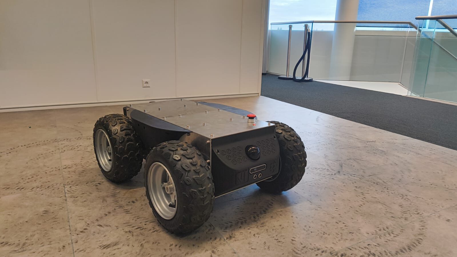
A skid-steer autonomous ground robot built to study navigation in the environments that break tidy assumptions — uneven floors, thresholds, scaffolding, and active construction sites. SLIP is the experimental platform behind an MSc Robotics research effort into sampling-based, uncertainty-aware navigation for unstructured terrain.
- ROS 2
- Nav2
- FAST-LIO2
- Jetson Orin Nano
- Skid-Steer UGV
01 — Overview
Most navigation stacks assume a flat, indoor floor, SLIP is built to run outdoors, on real ground.
SLIP (Scalable Locomotion for Imperfect Places) is an outdoor autonomous ground robot — an instrumented, all-terrain skid-steer UGV — built to traverse the terrain most navigation stacks never get tested on: uneven ground, loose rubble, thresholds, scaffolding, and the shifting floors of an active construction site. It exists to develop and validate autonomous navigation outdoors, in conditions well outside the flat, static floors most mobile robots are demonstrated on.
02 — The Robot Platform
Built rugged, instrumented, and CAN-driven
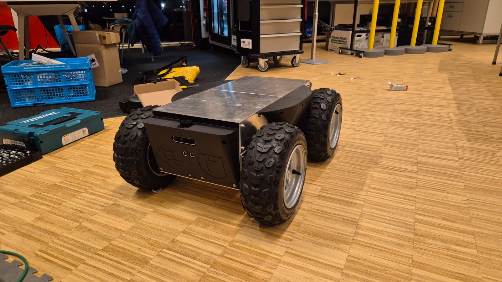
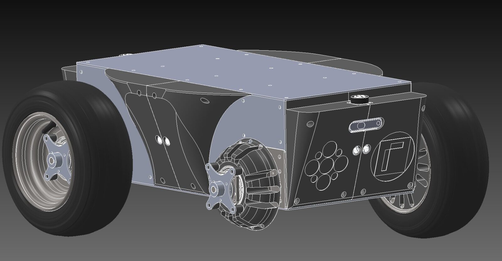
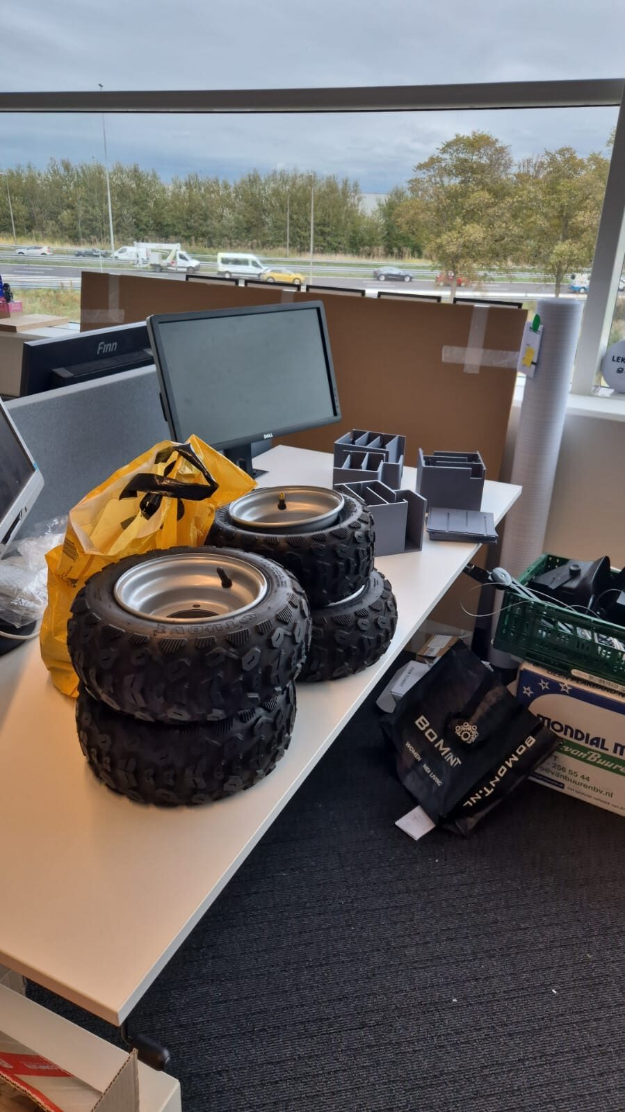
The base is a four-wheel skid-steer chassis with all-terrain tires, chosen for its simplicity and ability to traverse loose or uneven ground. Every subsystem — power, actuation, compute, and sensing — was integrated and, in the case of the motor control and sensor mounts, custom-built by hand.
Hardware
- Chassis4-wheel skid-steer, all-terrain tires, ≈1.52 m wheelbase
- ActuationODrive S1 motor controllers over CAN bus
- PerceptionIntel RealSense RGB-D · dual AiRY LiDAR (front + rear)
- IMUAdafruit BNO085
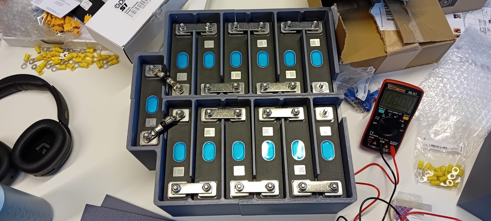
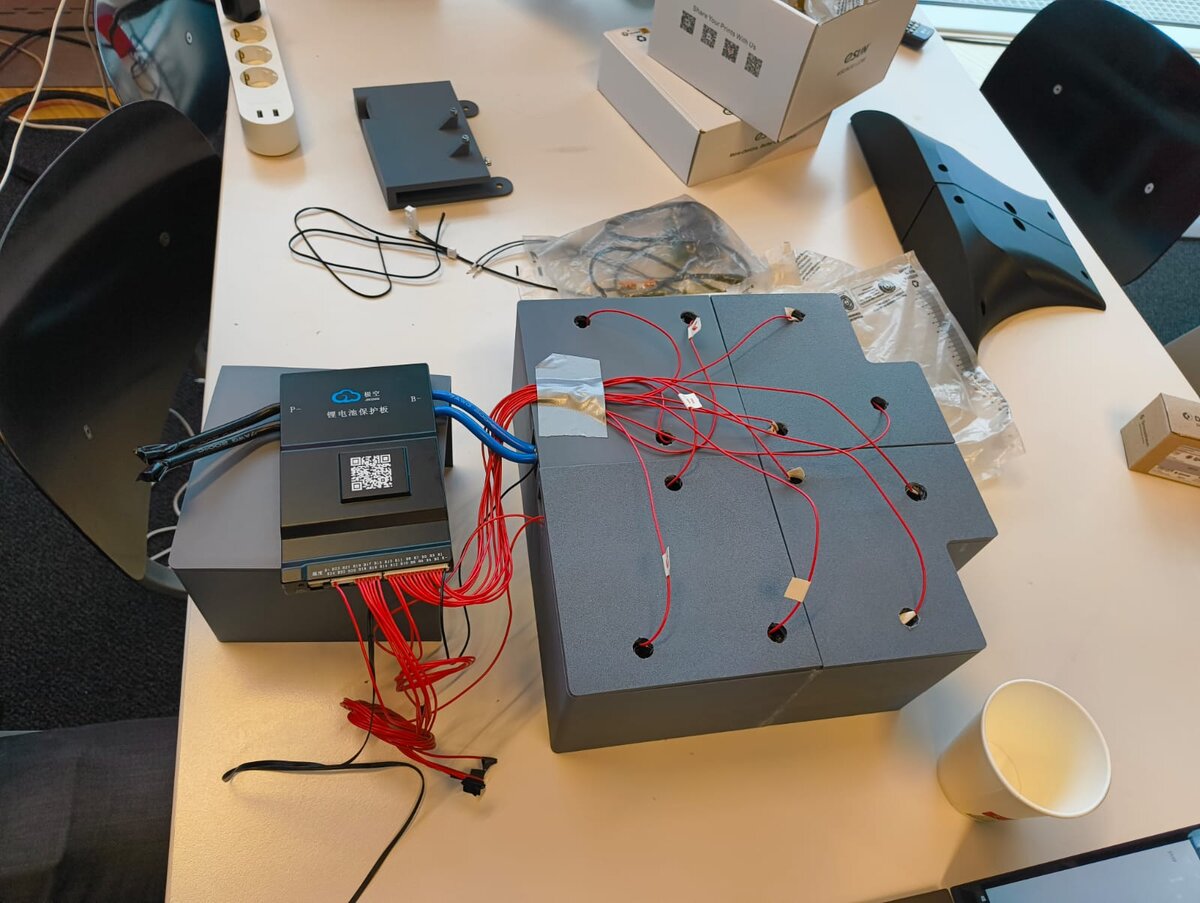
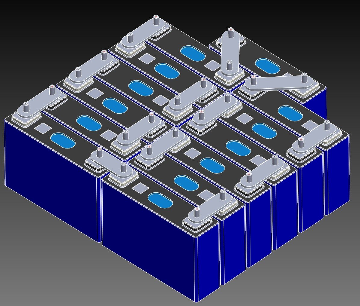
- PowerCustom Li-ion pack, 3D-printed battery enclosure
Compute & Software
- ComputeNvidia Jetson Orin Nano + SSD storage
- OSJetPack 6.2 (Ubuntu 22.04)
- MiddlewareROS 2&nbs
- ControlROS 2 diff-drive controller → ODrive over CAN
- Custom parts3D-printed LiDAR casing & battery mount, hand-soldered ODrive carrier board
03 — System Pipeline
Sensing to actuation, end to end
The current stack runs entirely on-board the Jetson Orin Nano over ROS 2. It was brought up incrementally — teleoperation first, then LiDAR odometry, then mapping and the Nav2 stack — and every stage was validated on hardware before moving to the next.
Sensing
LiDAR (front + rear)
IMU · RGB-D
State Estimation
RF2O / LiDAR odometry
+ EKF fusion
Mapping
Cartographer
→ migrating to FAST-LIO2
Planning
Nav2 stack
Control
ROS 2 diff-drive
→ ODrive CAN
Working on hardware today
- Teleoperation
- LiDAR odometry
- Full ROS 2 integration
- Nav2 stack running on-robot
- Autonomous point-to-point navigation
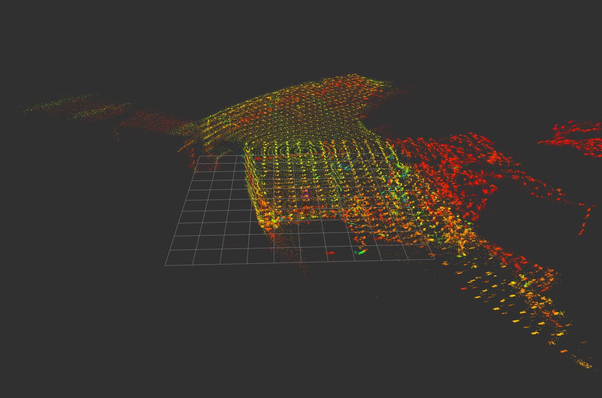
The arcing marks on the floor are SLIP's own wheel tracks from repeated trials.
Autonomous point-to-point driving inside the RoboHouse lab — holding a clean path around desks, carts, and neighbouring lab robots on shared floor space.
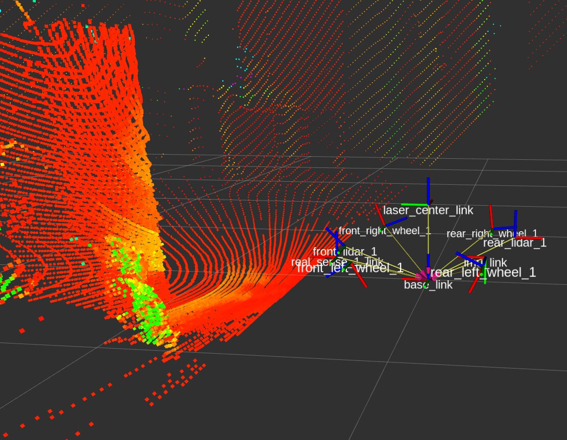
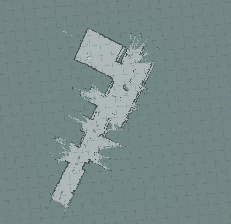
Perception & mapping, on real hardware
04 — Practical Challenges
What broke, and how it was fixed
In the weeds: what actually went wrong
The table above is the tidy summary. This is the longer, messier version in order, roughly, of how it happened.
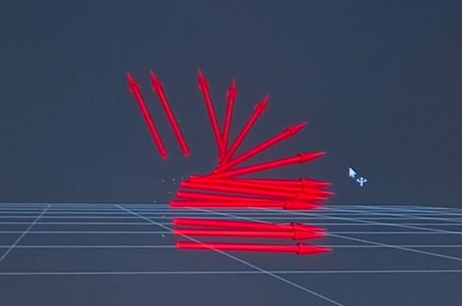
Getting FAST-LIO to say anything at all — then watching it fall apart
The LiDAR sits tilted 45° on the chassis 📐 — that gives it a much better view of the ground and a lot
more points to localise and map against, instead of losing itself in featureless open space. Getting
FAST-LIO to actually agree with that mounting was another story. I had to add a matrix-inverse
calculation into FAST-LIO's source to get the LiDAR's orientation right relative to base_link,
which meant pulling proper calibration values off the sensor first — thankfully FAST-LIO ships its own
calibration stack, or that would've been hell 😅. Next up was syncing LiDAR points and IMU readings onto
the same timestamp, which took its own share of trial and error. After a lot of runs that went nowhere,
it finally started tracking cleanly — yayyy, let's go 🎉
Trying nvblox as an alternative
I'd originally planned to get state estimation from visual-inertial odometry 📷 — it was my first time working with VIO and I wanted to get it running properly. I tried OpenVINS first, but camera-IMU calibration took forever to get right 🥲, and on top of that it turned out to be a much bigger compute bottleneck than expected for a Jetson Orin Nano — eventually I gave up on it. I switched to NVIDIA's nvblox instead and was genuinely happy with the runs I got out of it 🙌. Getting there wasn't trivial either — the Isaac ROS Docker container alone was around 46GB 🐳💀, and just wrangling that image onto the Orin Nano was an experience of its own.
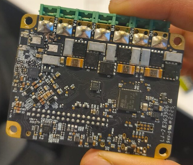
This is fine 🔥🐶
What's a robotics project if you don't burn a board or two along the way? We accidentally shorted one of the boards just a few weeks before the first checkpoint deadline — a proper "chuckles, I'm in danger" moment 😅. Nerve-wracking and stressful in the room at the time; hilarious in hindsight every time I look back at this photo now.
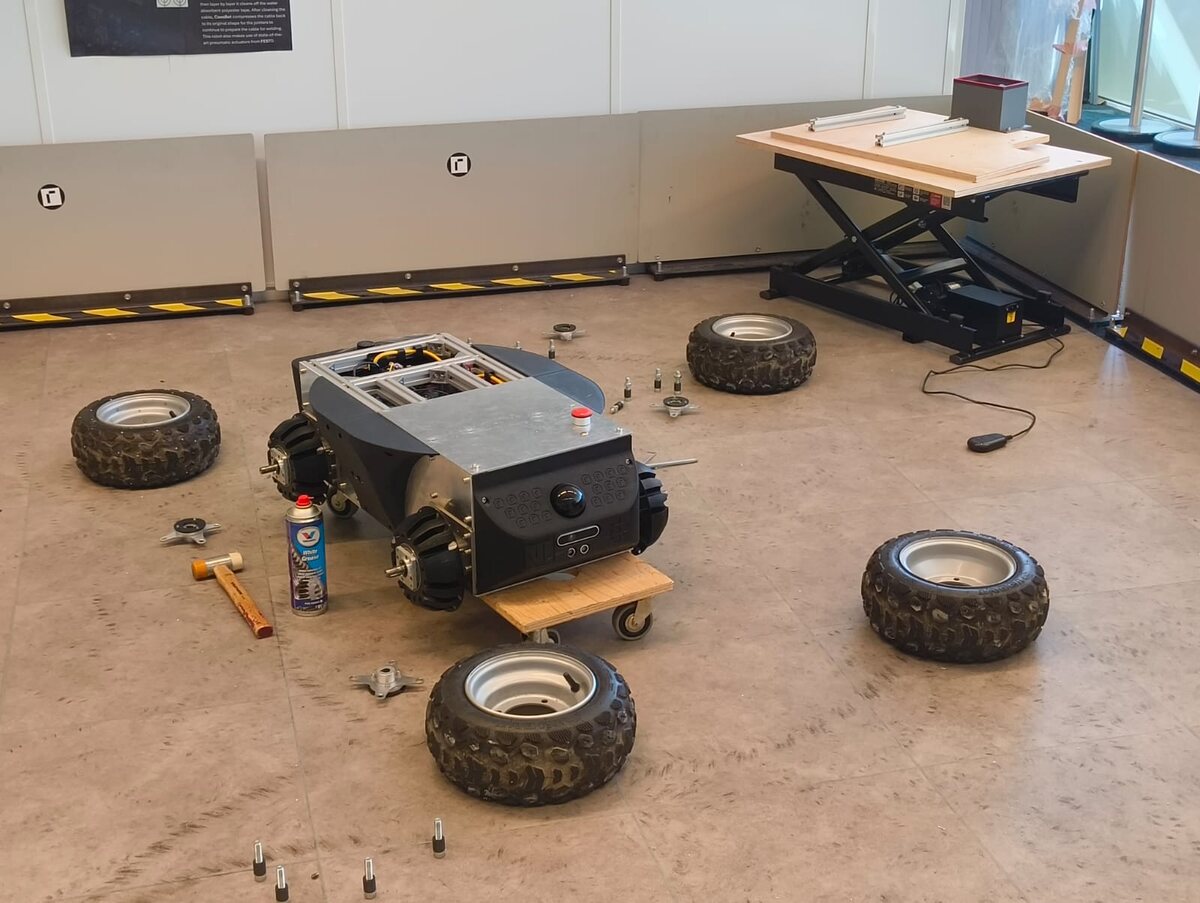
Wheel hubs, round two — my "007" phase
Around the lab this stretch got nicknamed "007": 0 successful trials on the first attempt, 0 times I didn't break something, 7 housings cracked along the way 🎯. SLIP weighs about 80 kg, so swapping anything on a prototype that size is already a slog — but I kept pushing it to find where its actual limits were. Top speed on paper is 3.6 m/s, and the PLA hub housings just couldn't take the torque out at that end of the envelope; they'd crack, and every time that happened I had to fully dismount and remount the gearbox to swap the housing in. A couple of times I even forgot to seat a gear on the way back together and had to redo the whole thing a second time 🙃.
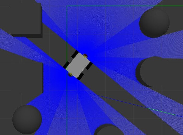
Testing in simulation first
Everything got built in gazebo sim first. The autonomy stack was tested there extensively before it ever touched hardware, and along the way I found a million ways to break things 🧵: SLAM maps scattering instead of converging, odometry that quietly drifted off, the robot refusing to move at all because torque and acceleration limits weren't set right, an unrealistic mass, wrong TFs on the wheels, wrong joint types, floor friction way too high, even the wrong axle length. I could go on — but every one of those mistakes is exactly what gives me the confidence now to know where to look and what to check the moment something breaks on the real robot. And on top of all that, porting ROS 1 packages to ROS 2 was its own special kind of irritating — most of what I wanted to test only existed on ROS 1, so it was either port it myself or go digging for a ROS 2 fork with two or three GitHub stars and hope it actually worked 😅.
05 — Field Trials
Off the lab floor: real construction sites
The clearest test of "imperfect places" isn't a lab — it's an active build site mid-fit-out: unfinished concrete, door thresholds, scaffolding, and material that needs to move. Across multiple site visits, SLIP was deployed to manually and semi-autonomously haul plywood sheeting, boxed material, and strapped blocks over exactly that kind of terrain — including an onboard scissor-lift platform for variable-height loads and raw paving-to-decking threshold crossings.
Filmed across multiple real sites and fit-outs, not staged demos — every threshold, cable run, and uneven patch of floor is exactly the kind of condition SLIP's navigation research targets.
06 — Research Direction
Toward uncertainty-aware, 3D-aware navigation
SLIP exists to test navigation ideas on a real, physically difficult platform rather than in simulation alone. The current direction centers on sampling-based stochastic optimal control for ground robot navigation — specifically Model Predictive Path Integral control (MPPI) as an approach to handling uncertainty and dynamic environments that classical planners tend to handle poorly.
Sampling-based stochastic control
Growing interest in sampling-based stochastic optimal control for robot navigation, with MPPI as a promising approach for handling uncertainty and dynamic environments in real time.
3D-aware MPPI
Current focus: MPPI variants that incorporate environment structure directly into trajectory sampling, rather than treating terrain as a flat 2D costmap.
LiDAR-based perception integration
Coupling the planner with FAST-LIO2 and a live point-cloud map, so trajectory sampling reasons about real 3D structure rather than a pre-built map.
Benchmarking
Comparing the resulting controller against classical planners on the same hardware, in the same unstructured environments.
Roadmap
- ~1 year of secured, dedicated access to the robot platform
- Develop a real-world outdoor test environment near RoboHouse
- Resolve networking & communication constraints for outdoor experiments
- Target a practical, socially relevant autonomous navigation system
- Exploring reinforcement learning as a complementary direction
- Contingency: Clearpath Husky UGV or simulation-based evaluation if hardware access changes
07 — Build Timeline
From bare frame to field trials
Thesis pitch & literature review
Research direction defined: sampling-based, uncertainty-aware navigation (MPPI) for an unstructured-terrain UGV.
Mechanical build & CAD
Chassis assembly, wheel/gearbox integration, and full mechanical CAD at the RoboHouse workshop.
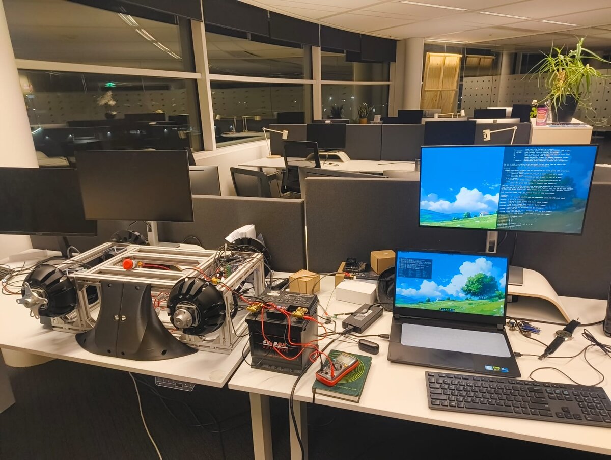
Early bring-up on the bare chassis, before there was a proper battery pack or onboard compute to speak of.
Electronics, autonomy stack & lab trials
ODrive integration, battery pack assembly, ROS 2 bring-up, LiDAR odometry, mapping, and the first autonomous point-to-point runs at RoboHouse.
The bare chassis under teleoperation — a laptop stood in for the onboard compute during early bring-up.
Field validation
Deployment on an active construction site: real payload transport over thresholds, scaffolding, and unfinished flooring — the environments the research is ultimately aimed at.
08 — About
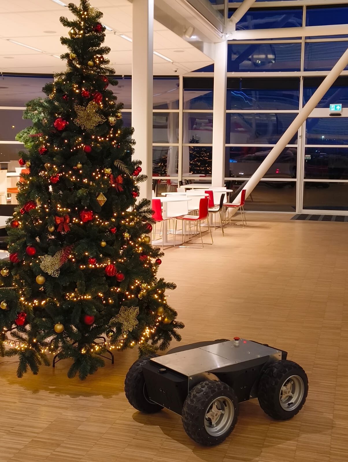
Saran Sundar Subbiah
MSc Robotics · TU Delft — Robotics / Software Engineer · RoboHouse
SLIP is developed as part of my MSc Robotics thesis work at TU Delft, in collaboration with RoboHouse, where I also work as a robotics software engineer. The project spans mechanical design, electronics integration, and autonomy software — and, most recently, taking that software out of the lab and onto a real construction site.